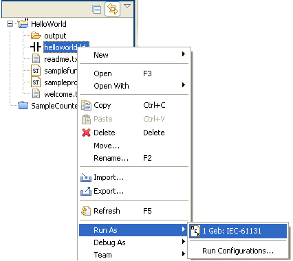
 right-click over the program file, in the Project
Explorer, select Run as... - GEB IEC-61131
right-click over the program file, in the Project
Explorer, select Run as... - GEB IEC-61131
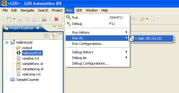 with the pou selected,
(Run- Run as... - GEB IEC-61131) or directly via the first menu option (Run - Run)
right-click over the program file, in the Project
Explorer, select Run as... - GEB IEC-61131
with the pou selected,
(Run- Run as... - GEB IEC-61131) or directly via the first menu option (Run - Run)
with the pou selected,
(Run- Run as... - GEB IEC-61131) or directly via the first menu option (Run - Run)
right-click over the program file, in the Project
Explorer, select Run as... - GEB IEC-61131
with the pou selected,
(Run- Run as... - GEB IEC-61131) or directly via the first menu option (Run - Run)
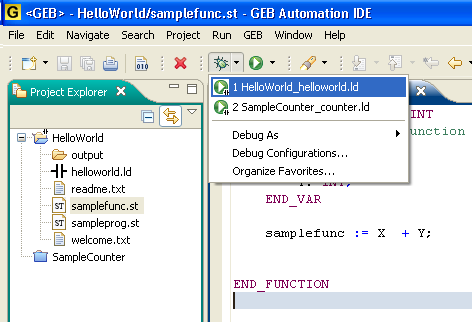
Actually, the direct "Run" command, from the menu or the Ctrl-F11 shortcut invokes the last "Run configuration". This is a standard Eclipse concept, which allows to create-edit-save-invoke several customized "launch configurations", for running or debugging. See the Eclipse help if you need more info.
A "Run" command will typically execute the program body and show in the console the values of its variables.
Bear in mind that the emulator that runs the IEC-61131 code is decoupled from the device definition, and hence it cannot emulate device-specific features of the project, such as mapping of directly represented variables, schedulling of POUs execution, etc.
To run a program in Debug mode:
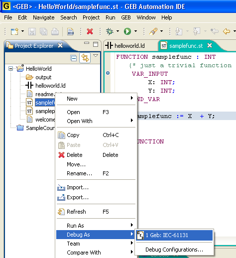 in the Project Explorer, select Debug as... - GEB IEC-61131
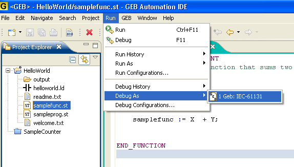 with the pou selected, (Debug- Debug as... - GEB IEC-61131)
 via the first menu option (Debug - Debug)
The execution will stop at the user defined breakpoints. From there, you can resume the execution or step over each instruction (F6). The Variables view will show the current values of each variable.
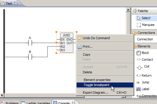
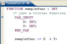 double click on the left margin, in the GEB Text Editor, over the line to place the breakpoint. A blue circle will appear.